Weather & rain information station (v17 May 2020)
Contents
Weather-station project
The outdoor sensor that measures the air temperature gave up on my existing indoors weather station. Recently I was reading about Arduino and what you could do with that. So I decided to built a weather station myself that downloads information from the internet for my local area. To make a long story short, after a lot of hours and putting lots of bits and pieces together ... this is the result:
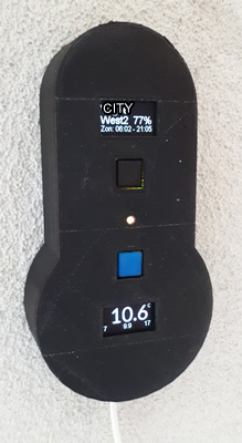
It has the following parts:
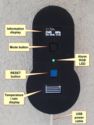
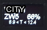
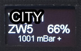
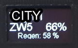
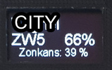
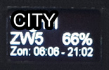
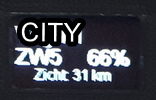
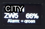
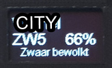
The information display has 3 lines. The top line gives the location, in my case my home town. The second line gives the wind direction and speed in beaufort. The third line is used to toggle between different bits of weather information.
0>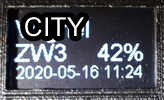 >1
>1
 >2
>2
 >3
>3
 >4
>4
 >5
>5
 >6
>6
 >7
>7
 >8
>8
- The time stamp when the information was downloaded from the internet.
- The minimum and maximum temperature of the last day.
- The air pressure in mBar. Followed by a trend sign. A minus means it has droppen in the last hour, a plus means it has increased. A double minus or plus or even a tripple indicates a stronger trend.
- The chance of rain that current day.
- The chance of sunshine that current day.
- The sun rise and sun set times.
- The visibility.
- The weather alarm for the region. Green means no alarm. Alarm comes in 3 stages, Yellow, Orange and Red (hence the RGB LED).
- A short hand description of the weather condition. "zwaar bewolkt" means "heavy overcast".
There are 2 buttons. The black one toggles the mode of the temperature / rain /solar display. The blue resets / restarts the ESP8266 controller. This is sometimes needed when the unit is no longer functioning.
The power supply can be any USB charger. The ESP8266 has a mini USB connector.
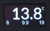
The temperature display has 3 modes, either show the temp, the rain or the solar data:
 <->
<->  <->
<-> 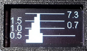
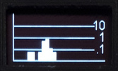
In temp mode it shows the actual outside temperature in the middle. This is in degrees Celsius since I live in the Netherlands. In the lower left and right corners it shows the predicted min and max temperatures for the day. In the middle lower it shows the wind chill / feel temperature. All this info is from the weather server. In rain mode it shows the expected rain in 5 min intervals for the next 2 hours. Each bar is a 5 min time span. The rain value send by the server is between 0 and 255, so a single unsigned byte. The scale is not linear but logarithmic. To make the display of the bars more meaningful I translate the values from the server into one that fits the display better (see this site and the sketch 3_loop for more info on this). The 3 horizontal lines are for 0.1, 1 and 10 mm/hour rain respectively. Finally, in solar mode the display shows the hourly energy production of the current day. The horizontal lines are 0.5, 1.0, 1.5 and 2.0 respectively. On the top right the total (so far) for that day is displayed in KWH and below that the energy production of the current hour.
The hardware
I decided on an ESP8266 unit that has built in WiFi. I also made a choice to have 2 displays, one for continuous display of the outside temperature and one for various other weather information. During development I also discovered a server that can sent the expected rain precipitation for the next 2 hours in my local area. So I added a rain mode for the temperature display.
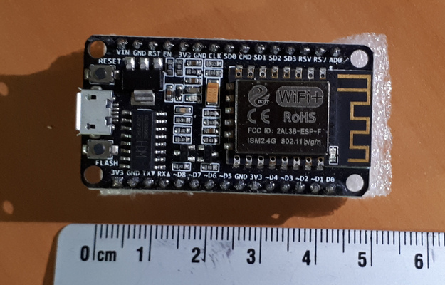
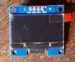
The ESP6288 is readily available on the internet, it is small and cheap. I bought 2 of these on-line, when I received the ESP8266 it turned out that one was rev E and the other was rev F. I did not experience any difference between these two. The OLED is a 1 inch size display with a resolution of 64 pixels vertical and 128 horizontal. These displays uses an SDD1306 chip and a so-called I2C interface with the ESP8266 controller. This requires only 2 connections. Together with a power and ground this means that these displays only have 4 pins. Be aware that the Power (VSS), GND (VDD), SCL and SDA pins are not on the same position between brands.
How it is all connected together.
First I used a breadboard to try everyhing out. I made a schematic for this using Fritzing. This is free-ware that is ideal for projects like this. In fritzing you can construct the breadboard setup and at the same time also the electrical connections. Fritzing has many built in parts that you can select and use in your project.
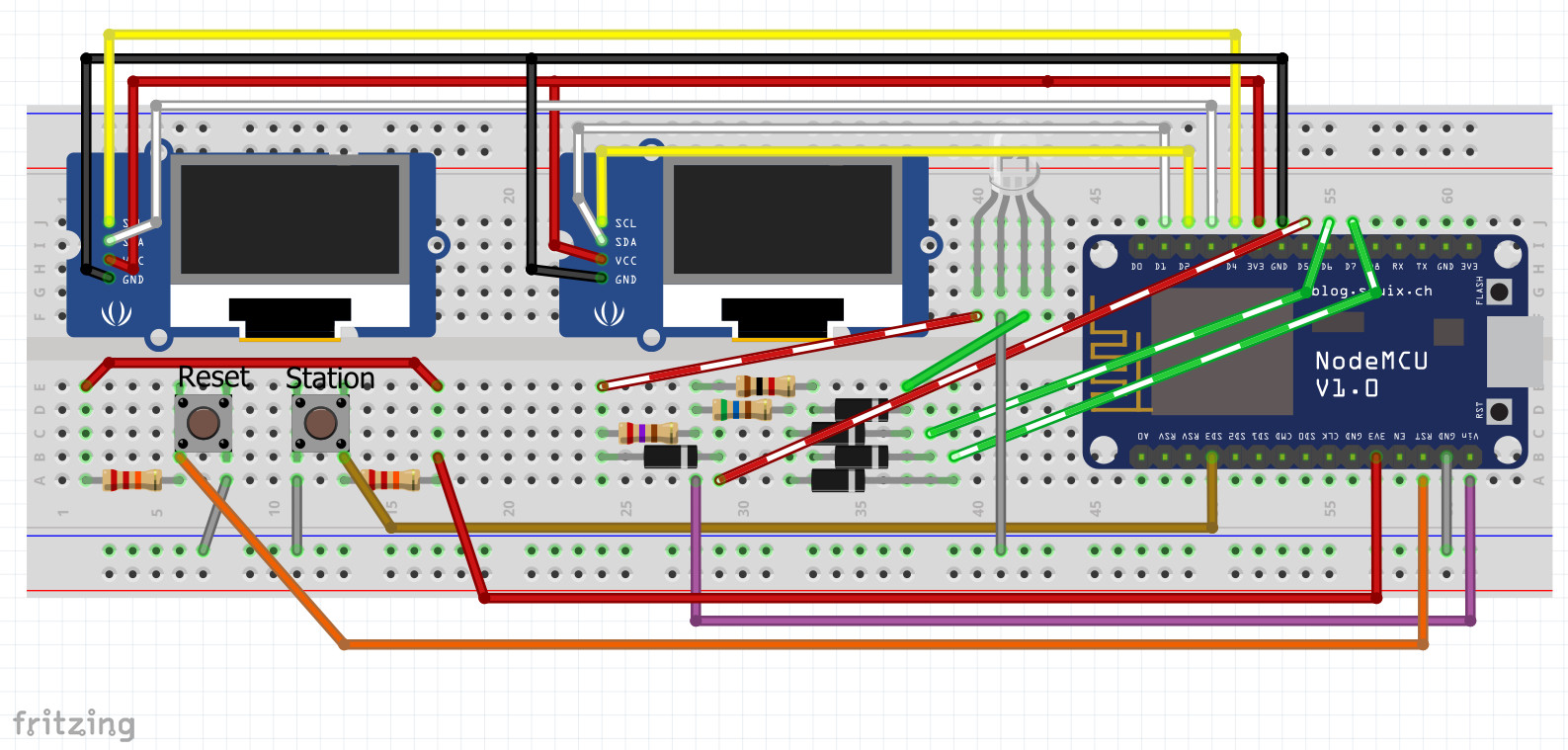
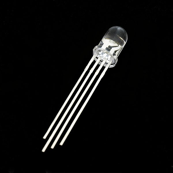
As you can see the displays and buttons connect directly to the ESP8266 controller. The situation with the RGB LED is a little more complicated. The ESP8266 internally works with a 3.3 voltage. This is too low to drive the RGB LED directly from the outputs. Therefore the USB power output Vin of 5 volt is used. With an output set to 0 the LED is off. The diodes are used to ensure that they can work independent from each other. The situation around the RGB LED is easier to understand if you look at the schematics:
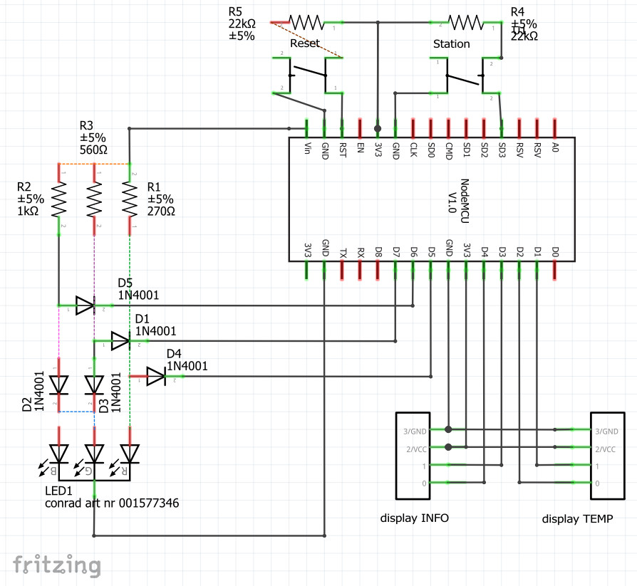
The blue LED is actually not used, only the green and red LED's. By driving only the red LED at 100% the color will be red. By combining the red and green you get yellow. With green at 50% and red at 100% you get orange. The difference between yellow and orange is quite subtle, therefore I added the alarm as text also to the weather info display.
The servers
The sketch uses 4 different servers to get all the information.
Weather information
The weather server gives information like temperature, wind strength and direction etc. This is a dutch server so it may only know dutch cities. In your browser you could check if this works by entering:
Browser URL = weerlive.nl/api/json-data-10min.php?key=PRIVATE_APIKEY&locatie=PRIVATE_CITY
The PRIVATE_APIKEY and PRIVATE_CITY you have to fill in yourself. The weather server sends back a response in JSON (Java Script Object Notation) format like this:
Weather info is grouped by tagname and tagvalue. E.g. "temp": "13.8" means actual temperature is 13.8 degree. The meaning of all the tags is explained in the 3_loop sketch. Not all tags are actually used in this project.
Rain information
This server uses GPS coordinates for the location. So this will probably work also outside the Netherlands. I have not tested this. The complete url for the browser would be:
Browser URL = gpsgadget.buienradar.nl/data/raintext?PRIVATE_COORDINATES
Browser URL = gpsgadget.buienradar.nl/data/raintext?lat=xx.x1&lon=x.xx
The rain server gives a rain prediction of roughly the next 2 hours.. It sends back a response like this:
000|17:25
000|17:30
010|17:35
032|17:40
056|17:45
011|17:50
005|17:55
000|18:00
000|18:05
000|18:10
000|18:15
000|18:20
000|18:25
000|18:30
000|18:35
054|18:40
145|18:45
070|18:50
000|18:55
000|19:00
000|19:05
000|19:10
000|19:15
Rain and time data separate by a pipe symbol. Of course the server also sends a header which is not shown here because the browser filters it out for the user.
Solar energy generated
The solar server gives the generated energy of our solar panels on the house of the requested day.
Browser URL = monitoringapi.solaredge.com/site/PRIVATE_SOLAR_SITE/energy?timeUnit=HOUR&endDate=2020-05-16&startDate=2020-05-16&api_key=PRIVATE_SOLAR_APIKEY
It sends a response in JSON format like this:
{"energy":{"timeUnit":"HOUR","unit":"Wh","measuredBy":"INVERTER","values":[{"date":"2020-05-14 00:00:00","value":null},,{"date":"2020-05-14 12:00:00","value":2010.132},,{"date":"2020-05-14 23:00:00","value":null}]}}For clarity I left out most of the intermediate hours. The value is the energy reproduction for the given time till the next hour. So the 2010.132 wh is generated between 12:00 and 13:00.
Date and time info
The time server gives the local date and time that the sketch needs. The date is used in the url to the solar server. The time is used in the solar display to give the energy reproduction of the current hour. The date and time together are shown in the info display to indicate last fetch of all information.
The weather, rain and solar servers give a timestamp in their header response but this is GMT time and not in the format I needed. A typical header response for example:
HTTP/1.1 200 OK

Date: Sun, 17 May 2020 10:49:03 GMT

Server: Apache/2.4.41 (Unix)

X-Powered-By: PHP/7.3.16

Content-Type: text/html

Connection: close

Transfer-Encoding: chunked
The month is in text, I needed it as a number. The time zone is GMT. So to use this I had to translate the month to a number and correct for local time. I decided on another approach and to use this website and my hosting provider as a 'time server'. Therefore, I made a small PHP program that returns the date and time in the format I needed. The time is local time and corrected for day light saving. This is the PHP program:
<?php
// timeserver
$currentDate = date("Y-m-d"); // e.g. 2020-05-16
$localTime = date("H:i"); // e.g. 08:34
echo <<<_END
yyyy-mm-dd=$currentDate<br />
hh:mm=$localTime<br />
_END;
?>
Saved this as a timestamp.php file on the website. When you type in the url to the file in the browser you get:
yyyy-mm-dd=2020-05-17
hh:mm=12:59
Because the browser filters / translates some of the response, the actual data received is:
yyyy-mm-dd=2020-05-17<br />
hh:mm=12:59<br />
So including the end of line brake tag of html. The sketch calls this url and from the response it is quite easy to extract the date and time.
The software
Used the free Arduino IDE v1.8.12 for the software. There is a vast amount of samples and libraries on the internet. Since I had not programmed an Arduino like controller before this was very helpfull to me.
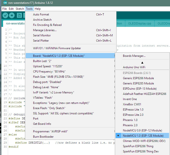
Make sure to set the correct board. For me this was the "NodeMCU 1.0 ESP-12E". The actual manufacturer of the board I bought is Geekcreit, this is compatible with the NodeMCU. Make sure you select version 1.0 of the NodeMCU and not 0.9. This is a different controller. For the ESP8266 board I downloaded the 2.6.0. library using the Arduino IDE.
During development of the code I split my sketch into different files. If the IDE finds different .ino files in your sketch folder then it will display a separate tab for each of them in the user interface. This makes it easier to edit the code. The IDE will execute the 'main' sketch first and then the other sketches in alphabetic order. Basically in the order of the tabs from left to right. In the IDE screen shot below you can see that I have 6 sketches:

- ron-weerstationv18. This is the main sketch
- 0_private. This is where I define some constants which are private, like WiFi SSID and password. These constants all start with PRIVATE_
- 1_definition. This is the first part of the program where variables and constants are defined.
- 2_setup. This is the code that will be executed once by the controller. Used for instance to make WiFi connection.
- 3_loop. This is the code that is constantly executed in a loop.
- 4_functions. Here small pieces of re-usable code is placed. I ended up with this file empty.
The IDE also loads any .h and .cpp files it finds in the sketch folder. These are library files that I modified for my project.
Sketch: ron-weerstationv18
This sketch is very small. It explains the project in comments. It loads 2 libraries specific for my project:
The ESP8266WiFi library contains many other libraries that are needed to connect the ESP8266 to my WiFi and to connect to an internet server.
Furthermore this sketch defines if debugging output is on or off.
// debugging macros
//#define DEBUG				// Remove comment for DEBUG mode!
#ifdef DEBUG
	#define DPRINT(...)		Serial.print(__VA_ARGS__)
	#define DPRINTLN(...)	Serial.println(__VA_ARGS__)
#else
	#define DPRINT(...)		//now defines a blank line i.e. no print output
	#define DPRINTLN(...)	//now defines a blank line i.e. no print output
#endif
With this construction you can switch on or off all output to the serial monitor by changing one line.
Sketch: 0_private
// define private constants
const char* PRIVATE_WIFI_SSID = "";
const char* PRIVATE_WIFI_PASSWORD = "";
const char* PRIVATE_WEATHER_APIKEY = "";
const char* PRIVATE_CITY = "";
const char* PRIVATE_COORDINATES = "lat=xx.x1&lon=x.xx"; // GPS coordinates of your locations
const char* PRIVATE_SOLAR_APIKEY = "";;
const char* PRIVATE_SOLAR_SITE = "your solar site id";
const char* PRIVATE_URLT = "your time page";
In the download this text is included in the sketch and not the original sketch.
The solar and weather server will only send a response if a correct key (APIKEY) is included in the url. The key has to be requested once by a user from the server using the browser and replaces the text PRIVATE_APIKEY. The servers allows 300 downloads per day. This is enough to update information every 5 min.
Sketch: 1_definition
Here the constants, variables and objects are defined that are used in the program. Most are straightforward, I will highlight only a few:
// Initialize the OLED display using Wire library
SSD1306Wire  displayInfo(0x3c, D3, D4); // SDA=D3 SCL=D5, INFO display for weather info
SSD1306Wire  displayTemp(0x3c, D1, D2); // SDA=D1 SCL=D2, TEMP/RAIN display
The SDD1306Wire library is needed for the OLED displays. Two instances of the class SDD1306Wire are made because there are 2 displays used independently.
WiFiClient clientH;			// to connect to an insecure (HTTP) internet server
const int httpPort = 80;

WiFiClientSecure clientS;	// to connect to a secure (HTTPS) internet server
const int httpsPort = 443;
Also two TCP clients are used, one for server that use a secure connection (starting with https:) and for those that use an insecure connection (starting with http:). They both use different ports. Port 80 is the default port for HTTP, 443 is the default for HTTPS. The sketch makes connections to 4 different servers, the time, rain and solar servers use the clientS and port 443. The weather server uses clientH and port 80.
// enumeration for modes button
enum DISPLAY_MODE {DISPLAY_MODE_WEATHER = 0,DISPLAY_MODE_RAIN = 1,DISPLAY_MODE_SOLAR = 2};
To make the code a bit more readable I named the 3 modes that are used for the temp display. With the given enumeration a variable can be assgined to a specific mode as DisplayMode = DISPLAY_MODE_RAIN
// define  global variables (start with uppercase letter, local variables start with lower case)
String CurrentDate = "2020-01-01";
String CurrentTime = "00:00";
The date is used in the solar url to get the info of today. The date and time are both displayed as an indication when the data was last fetched.
Sketch: 2_setup
In this sketch the pins of the ESP8266 are set to the correct mode. They can be used for input of output so this has to be defined.
The serial port for the debug messages is initialized and set to maximum baud rate.
The OLED displays are both initialized. Initially, I could not get the 2 displays to both work at the same time. I ended up adding the following code found on the internet:
	// This will make sure that multiple instances of a display driver
	// running on different ports will work together transparently
	displayInfo.setI2cAutoInit(true);
	displayTemp.setI2cAutoInit(true);
Sketch: 3_loop
This is were all the work is done. The code can be broken down into:
- Connect to local WiFi network.
- GET date and time from the time server
- GET data from the weather server
- GET data from the rain server
- Write data to the INFO display
- Read black button and toggle mode rain/temp/solar
- Write temperature or rain data or solar data to the TEMP/RAIN/SOLAR display
- Drive alarm RGB LED
- Manage loop counters. Change function mode every 3 seconds. Fetch data again from servers every 5 min
The steps that are followed to get data from an internet server can be made visual as follows:
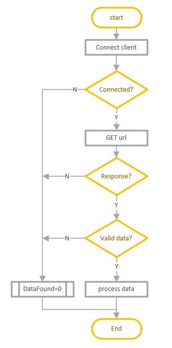
When no data is found this is used when displaying the information on the displays.
When making a connection to an in-secure HTTP internet server, getting data and processing it the following code / steps are importent:
- Connect to the server:
clientH.connect(hostH, httpPortH) - Send a URL request to the server:
clientH.println("GET " + url + " HTTP/1.1");: Format is predefined. Notice space before HTTP.
clientH.println("Host: " + String(hostH));: Mandatory
clientH.println("Connection: close"): This tells server to close connection after response.
clientH.println();: This indicates end of header to the server. - Wait some time for server to respond
- Read buffer, extract payload data
- Empty the buffer completely:
while (clientH.available()) int x = clientH.read();
When making a connection to a secure HTTPS internet server the steps are almost the same:
- Tell the client to use an insecure connection :
clientS.setInsecure(); - Connect to the server:
clientS.connect(hostS, httpsPortS): Notice now a https port nr is used. - Send a URL request to the server:
clientS.println("GET " + url + " HTTP/1.1");: Format is predefined. Notice space before HTTP. Notice that 'S' (from https) is not included.
clientS.println("Host: " + String(hostS));: Mandatory
clientS.println("Connection: close"): This tells server to close connection after response.
clientS.println();: This indicates end of header to the server. - Wait some time for server to respond
- Read buffer, extract payload data
- Empty the buffer completely:
while (clientS.available()) int x = clientS.read();
Although the servers are secure servers the actual connection made by the weatherstation to the servers is insecure! This means that you cannot be 100% confident that received data is valid and indeed from the expected server. Because I am only reading generally available data and not sensitive information I believe this is not a risk. In the unlikely event that the weather stations does get hacked then it would stop working and not impose a intrusion risk for my house, the weather station is a standalone device. To make a secure connection a so-called fingerprint is needed to verify server connection. The problem with this fingerprint is that it is only valid for a limited period, say a year. A browser will refresh the fingerprint seamlessly for the user but with an Arduino device you have to hard code the fingerprint in. So after a while when it expires you have to change the code. A fingerprint would be something defined as a constant in the definition section, example:
const uint8_t fingerprint[20] = {0x5A, 0xCF, 0xFE, 0xF0, 0xF1, 0xA6, 0xF4, 0x5F, 0xD2, 0x11, 0x11, 0xC6, 0x1D, 0x2F, 0x0E, 0xBC, 0x39, 0x8D, 0x50, 0xE0};Then instead of the line clientS.setInsecure(); you would have used the line clientS.setFingerprint(fingerprint);
To obtain a fingerprint for a website, go to the site using the chrome browser and press F12 or Ctrl-Shift-i to inspect the page. Then select the security tab and view certificate:
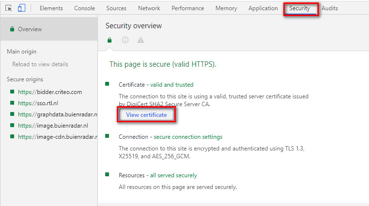
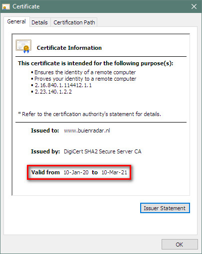
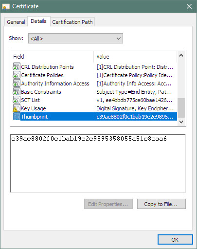
A small pop-ip window opens where on the general tab you can see the expiration date and on the detail tab you can get the actual fingerprint that you can paste in the sketch:
Font
For the temp reading in the TEMP display I wanted a large pixel font that would just fit the display and could be read from a distance. The standard library did not have such a large font. On the internet I found this site where you can create your own font. I then copied the generated code into the OLEDDisplayFonts.h file. Because I modified the font I placed the OLEDDisplayFonts.h file in the sketch directory. This ensures that the modified library is used in stead of the standard library. Within the code you can select this font with the line:
displayTemp.setFont(Lato_Regular_52);Libraries
A library is a collection of tools / functions / code to for a specific goal. These are very useful and save a lot of deep dive development and hours. A single library (usually) consists of 2 files. A so-called header file with the definitions and with the extension ".h" and the program code for the library with extension ".cpp". As mentioned above a library can be used in a sketch with the command #include "library". Note that the OLEDDisplayFonts library only has a header file. This library only has a definition and no actual code. A library can itself also include other libraries. This is usually actually the case. So it is not always clear what libraries are involved in a sketch. This is also usually not much of a concern. The Arduino IDE will take care of that.
Libraries can reside in different location on your computer:
- In the sketch folder
This is where I stored my modified library for the font and a downloaded library for the interface with the OLED displays.
This folder can be in a location of your choice. I place mine on my NAS drive but it could also be in the windows C:/Users/XXX/Documents folder. - In the board folder
As mentioned earlier you should select your board in the Arduino IDE board manager
This also downloads the libraries specific for your board. At my computer this was stored in C:\Users\ron\AppData\Local\Arduino15\packages\esp8266\hardware\esp8266\2.6.1 - In the Arduino IDE folder
These are general purpose libraries that come with the installation of the Arduino IDE
I am using version Arduino v1.8.12 on Windows 10. The libraries are stored in C:\Program Files (x86)\Arduino\libraries
I believe this is also the order in which the Arduino IDE will look for a library that must be included. I was able to 'override' the OLEDDisplayFonts library by placing it in the sketch folder directly. Click here to read more about libraries on the Arduino website.
My sketch includes 2 libraries, the ESP8266WiFi.h which is one of the board libraries and the SDD1306Wire library that I downloaded from the internet and is in the sketch folder. The IDE will include many more libraries during compilation that are included but probably also libraries that are not explicitly included but part of the core.
Memory usage
I believe my sketch is not very memory friendly. Have used a lot of Global String variables and Global String constants. That is, String with a capital 'S'. The String object has a lot of manipulation functions, this makes it easy to use but also adds some overhead to each variable. For instance you can use the function InputLine.indexOf("Date:") to find out if the text "Date:" is present in the String InputLine. This is more dificult with a char array.
Here is a memory report from the compiler for different situations:

The important values I have highlighted in red text. As you can see with an empty sketch there is already a significant amount of memory used. The total sketch adds to that, but the increase is not a lot. The IRAM value seems the most critical. It also seems to be the one that at sketch level you have the least control over. The IRAM is a 32k bytes of dynamic RAM memory that is used to run sketch code (if I googled this correctly) 4 times faster than it would from ROM. Normally most of the code is run from ROM. What goes here is determined by the developers of the libraries used. This is beyond my programming capabilities. Therefore I decided not to try to improve memory usage in my sketch.
PS1 in the above table the DATA (initialized global variables), RODATA (=Read Only DATA, global read only variables) and BSS (non initialized global variables) together are the nr of bytes in the GlobalVar column. The ESP has 80k (dynamic read/write SRAM) memory for GlobalVar, this is used to calculate the percentage. So this means that roughly 60% of 80k = 50k is available during runtime of the program.
PS2 The IROM value in the table is the nr of bytes the sketch occupies in ROM or flash memory. Since there is plenty of flash memory on the ESP8266 this is not a limitation for the sketch. Apparently you can also flash the ESP8266 wireless (called OTA = Over The Air) but I have never tried this. I always flash using USB connection.
So how about the memory when the program is running? This paints a different picture. You can use the function ESP.getFreeHeap() to retrieve the amount of memory left for the running program to work with and ESP.getHeapFragmentation() to get the amount of free gaps within the heap. For an empty sketch the free amount is around 49000 bytes. With the full sketch running this reduces to 16000 bytes. This is a more dramatic decrease. Initially, after activating the sketch the heap fragmentation is 4%. When code is running for a longer time the free space reduces a bit to around 15000 and the fragmentation increases to 25%. This seems to stabalize around these values. I do not really see a need to improve this so decided to leave it for now. You can read a bit more on this topic on this site
The housing
Since I have a 3D printer I decided to design and print a housing myself. For the design I used a thermometer shape. The size of the housing is 150mm. So most 3D printers should be able to print this.
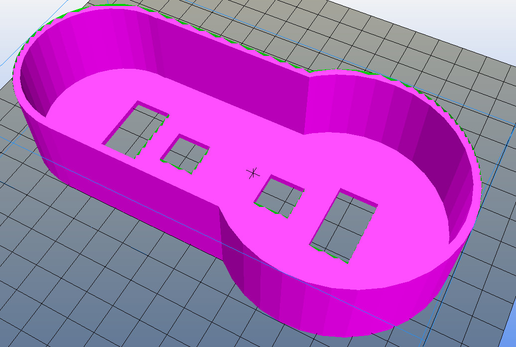
The picture is a screenshot of a 3d print software program. The view is from the back.
Download
The Arduino IDE and the board libraries you have to download from the internet.
Download the ZIP file with all sketches incl modified libraries. Do not copy the downloaded folder to your Arduino sketch folder using windows, instead use the Arduino IDE to include a ZIP library. Sketch folder contains also the weather and rain server response on which the sketch was based.
Download the Fritzing file. The Fritzing software you have to download from the Fritzing site.
Download the STL file for 3d printing.